Delco Remy Starter Generators – How They Work and Testing

29 Chev

Tractorologist
Senior Member
Member
Please be aware this information is presented AS IS – USE AT YOUR OWN RISK AND EXPENSE

Please note some measurements stated are what were observed while working on a Bolens 1050 tractor with a starter generator 1101970 – other Delco Remy starter generators may be different.

It is my hope that this article will provide the reader with a basic understanding of how a 12 volt Delco Remy Starter / Generator works on a garden tractor application to start an engine and also to charge the battery back up once the engine is running. This information should make it easier for the reader to diagnose and troubleshoot a charging or starting problem and at the same time provide a working knowledge of the system components involved. I will attempt to keep the technical part of the learning process to a simple level that most people with some basic knowledge of electricity can understand.

For those following along if I post something that you do not understand feel free to ask and I will try and answer any questions as best I can. I am not an electrical expert and if I post information you feel is wrong please advise as this is how we all learn.

For those who want a deeper working knowledge they can refer to the Delco Remy service bulletin IMG-150 which I will also attach as a pdf copy.
 

Attachments

  • IMG-150 Delco Remy Service Bulletin.pdf
    727.1 KB · Views: 8
Let us start this journey by stating that electricity can be used to rotate a shaft in an electric motor and that the shaft in an electric motor can be rotated so it creates electricity. In simplistic terms this is what a starter generator is doing using an electromagnet and coils of wire placed near each other with the electromagnet being stationary and the coils of wire rotating very near to it. An electromagnet is simply a coil of insulated wire (usually copper) that is wrapped around an iron core and when the coil of wire is connected to a battery to form a circuit an electric current will flow making the iron core a powerful magnet. If the battery is disconnected by opening the circuit current will stop flowing and the magnetic properties of the iron core will be minimal. The process is a bit more complicated than what I have described but suffice it to say that when a starter generator functions as a generator a magnet is moved across a coil of wire and electricity is generated. A current with a voltage level is created that can be connected by wires to form a circuit and used to charge up a battery. In this case the starter generator is supplying electricity and the battery is acting as the load. Similarly when a starter generator is used as a starter a storage battery can be connected to the starter generator with wires to form a circuit and current with a voltage level can flow from the battery to the starter generator and be used to make the shaft of the starter generator rotate. In this case the battery is supplying electricity and the starter generator is acting as the load.
I have mentioned several words which may be unfamiliar to the reader and since they must be understood to move on let us take a bit of time and learn what each word means.

Starter Generator
A starter generator is a device with a pulley that can be used as an electric motor to rotate an engine or can be rotated by an engine to produce electricity. It can be connected with a belt to rotate a crankshaft pulley on an engine – in this case it is being used as a starter. It can also be used while being driven by the belt once the engine is started to create electricity. A starter generator was also called a motor generator by Delco Remy.

Storage Battery
A storage battery is a device that can be used to store and supply electricity for a period of time. While the electricity is contained inside the battery it can be said to have potential energy. When a charged battery is connected to a circuit current can flow to a load so that the electricity can be converted into something else such as motion (electric motor) or light (headlight). When it is allowed to flow the electricity is converted from potential energy into kinetic energy so that it can do work. If the battery is connected to a generator the generator can be used to recharge any electricity that has been removed from the battery. In most garden tractor applications using a starter generator the battery will have a voltage rating of 12 volts. It should be noted that the voltage level of a good battery when measured at the battery will usually vary between approximately 9.5 and 14.5 volts depending on the status of the charging system and whether the battery is providing or receiving electricity.

Load
A load is any device that can be connected via wires to a battery so that current can flow though the wires to supply electricity to the load so that the load can convert the electricity to something else. An electric motor is one example of a load as it converts electricity into motion so that the shaft rotates. Another example of a load is a head light that converts the electricity to light.

Circuit
A circuit is formed when one or more wires are connected between a storage battery and a load so that current can flow from the storage batteries two terminals to the load. An example of a circuit would be if a wire is connected to the positive post of a battery and one terminal of a headlight and another wire is connected from the other terminal on the headlight to the negative post of the battery. The two wires form a circuit so that current can flow from the battery to the headlight. It should be noted that sometimes the sheet metal, frame or the engine block are used on garden tractor applications to replace a wire as part of a circuit.

Current
Current is the flow of electricity in a circuit – it is the part of electricity that does the work and is measured in amperes. The word ampere is often shortened to amp (or amps) for convenience and refers to the amount of current that passes a given point in a specific time. Current flowing in an electrical circuit can be compared to water flowing inside a water pipe in a plumbing system – a water meter can be used to measure how much water passes a given point in a specific time. In a plumbing system it would probably be measured in gallons per hour – in an electrical system the current flow is measured in amps.

Voltage
Voltage is the difference in the level of electricity when measured between two points in a circuit and is measured in volts. Voltage can be equated to pressure in a water pipe and the higher the pressure in a water pipe the more water can flow during a specific time period through a pipe. Similarly, in an electrical circuit, the higher the voltage level in a circuit the easier it is for more current to flow between two points in the circuit in a given period of time.

While the above explanations are simplistic and do not cover in depth what each word means they should enable the reader to grasp their meaning so they can understand things when we talk about them in relation to a starter generator.
 
Delco Remy Starter Generators – A Little History

Back about 1955 the majority of manufacturers in the automotive industry switched from using a 6 volt electrical system that could be configured as either positive or negative ground to a more standardized 12 volt negative ground electrical system in cars and other vehicles. As engine compressions were on the rise and more electrical accessories were being added it had become apparent that 6 volts systems were inadequate to supply the necessary electrical demands of new vehicles. Starters and generators could be redesigned using lighter windings to provide more efficient ways of starting an engine and keeping things powered as the engine propelled the vehicle down the road. In vehicles generators would eventually be replaced with alternators about 10 years later but with the switch to 12 volt systems and the evolving rise in garden tractor demand the small engine market was seen as another area for potential growth and sales. With bigger and better tractors and an increase in engine horse power the need became apparent that an electric starting device for small engines was required by garden tractor and other manufacturers. With such a starting device a generator would also be needed to charge and maintain a battery as well as supply power for lights and other accessories. Since there were other applications such as marine, aircraft, lighting plants, etc. where a combination starter generator equipped engine would also prove useful Delco Remy researched and produced a starter generator to meet the needs. Since the starter generator was a combination starter and generator unit with a pulley it could easily be adapted with a belt and mounting bracket to provide electric start and generator capabilities to a vast number of small engine applications.

The Good And The Not So Good

While the addition of the starter generator revolutionized the small engine industry it was far from a perfect solution. It did provide an easy way to start and stop the engine and provide a way to recharge the battery and supply power to light a couple of headlights which was good. The use of a V belt was often a draw back as it required periodic adjustment so that the belt did not start slipping in the starter generator pulley. If the belt was allowed to slip very often it would wear quickly and then need replacement. The Delco Remy starter generator was usually a sealed unit with no cooling holes so the starter generator would get quite warm to the touch quickly with use and current output was usually designed to be limited to about 10 amps. It should be noted that a generator is not self limiting when it comes to current output and as a result requires a regulator that will function to limit both current output and voltage output in a charging system. If a badly discharged battery was connected directly to a generator without any current regulation the battery would draw all the current the generator was capable of producing. This would not be good as the more current that was being drawn the hotter the generator would get and eventually the generator would be damaged from the excessive heat if this was allowed to continue for very long. The regulator must also have some type of switch built into it so that if the generator is not producing current (such as at idle or with the engine off) the connection to the battery can be opened so that the generator does not act like a motor and draw current out of the battery. Most starter generators will not produce useful current unless the engine driving it is running about 1300 rpm or higher. For these reasons (as well as others such as size, weight and cost) as advances were made most small engines switched to a Permanent Magnet Alternator charging system and a separate starter motor that engaged with a ring gear in the mid 1970’s.
 
How the System Works As A Starter

Now that we have discussed the history let us now move on and study how the starter generator interacts with other components to start an engine and also provide electricity to recharge the battery once the engine is running.

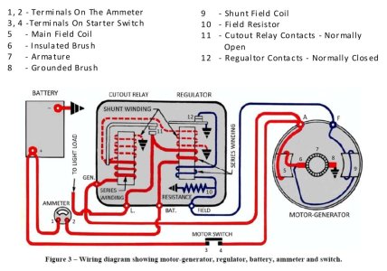
Here is a wiring diagram from the Delco Remy Service Information of a storage battery, a voltage regulator and a starter generator as it might be connected in a generic application.
1A Delco Remy Two Terminal Motor Generator.jpg
As can be seen we have a 12 volt battery, an ammeter, a normally open push button motor (starter) switch, a regulator that has a cutout section and a combination voltage and current regulation section (housed in what is commonly called the regulator) and the motor (starter) generator. The battery has a positive and negative terminal – the negative terminal is connected to ground with a battery cable and the positive terminal is connected to terminal (1) on the ammeter via one wire and to the normally open push button starter switch terminal (3) with a battery cable. The starter generator has two terminals – one is marked A which stands for Armature and the other is marked F which stands for Field. The regulator has four terminals marked GEN which stands for Generator, L which stands for Load (or Lights), BAT which stands for Battery and F which stands for Field. There is one wire that connects the A terminal of the starter generator to the GEN terminal of the regulator. There is also a battery cable that connects the A terminal of the starter generator to terminal (4) of the normally open push button starter switch. The BAT terminal of the regulator is connected to the other terminal of the ammeter. Both the starter generator housing and the voltage regulator body are connected to ground which completes circuit connections for some of the internal components.

Let us examine the various circuits when the starter generator is used to set the engine in motion to get the crankshaft of the engine to rotate. It should be mentioned that when the starter generator is initially energized both it and the engine is at rest so there will be a large amount of current required to make the starter generator begin to rotate and begin rotating the crankshaft of the engine. All connections must be good and clean and the cables that connect the A terminal of the starter generator to the push button switch and the push button switch to the positive terminal of the battery must be in good condition (no internal corrosion) and of heavy enough gauge to allow adequate current flow – they are usually a minimum of 4 gauge cable. Similarly any connections in the ground circuit must also be tight and clean so that adequate current can flow in this part of the circuit to the negative battery post.

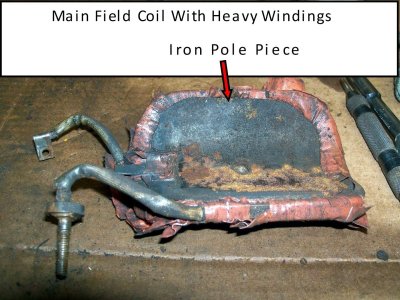
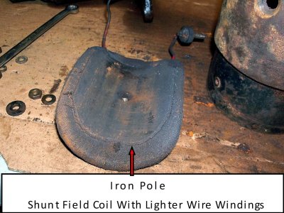
It should also be noted that the Main Field Coil (5) in the diagram is wired in series with the armature and that the Shunt Field Coil (9) is wired in parallel with the armature. This simply means that the current coming from the battery must flow through the Main Field Coil and also flow through the brushes and Armature windings to reach a ground point whereas the current flows directly through the Shunt Field Coil to a ground point. Both the Main Field Coil (5) and the Shunt Field Coil (9) are used to create electromagnets when the starter generator functions as a starter motor but only the Shunt Field Coil (9) is used as an electromagnet when the starter generator functions as a generator. The Main Field Coil (5) consists of a very heavy gauge flattened piece of insulated copper wound around an iron core pole and the Shunt Field Coil (9) consists of many turns of much lighter wire wound around an iron core pole.

In the diagram above if the motor switch (normally open push button starter switch) is pushed this will close the circuit between the positive terminal of the battery and the A terminal of the starter generator. Current will now flow to the A terminal of the starter generator, through the Main Field Coil (5) to an insulated brush (6), one of the segments of the commutator of the Armature (7), through the windings of the Armature to another commutator segment located 180° around on the armature, through the other grounded brush (8) and then back to the battery via the ground side of the circuit which is connected to the negative post of the battery. The Main Field Coil (5) and the windings in the Armature (7) will become electromagnets with opposite polarities making them repel each other and the armature will start to rotate. At the same time current will also flow directly through the Shunt Field Coil (9) which is connected to ground via the F terminal of the starter generator and the Field terminal of the regulator through the normally closed contact inside the regulator (12). It should be noted that the Main Field Coil (5) is the primary Field Coil used when the starter generator is used as a starter and the Shunt Field Coil (9) contributes to a lesser extent during the starting process to form the two electromagnets which repel the armature and cause it to rotate. Once the starter generator and the engine crankshaft begin to rotate the current draw at the starter generator will decrease slightly (since both the starter generator and the engine crankshaft are now in motion) and the engine will continue to rotate as long as the starter switch is held closed or the battery discharges to the point it can no longer supply enough current to keep the armature rotating. As the armature in the starter generator rotates heat will begin to develop inside the starter generator and the starter generator will begin to get warm. To keep any heat build up to a minimum inside the starter generator it is recommended that the switch only be held closed for a maximum of 15 seconds and then the starter generator should be allowed to cool for a minute before trying to start the engine again. It should be noted that a normal engine in good tune should start within 15 seconds and if it does not it is highly recommended that the cause of the poorly starting engine be corrected to reduce wear and heat damage inside the starter generator.

Once the engine starts the normally open push button starter switch is released and the circuit that caused the starter generator to act as a motor is now once more open. The engine is now turning the armature inside the starter generator and now the starter generator can be used as a generator to produce electricity.
 
How the System Works As A Generator
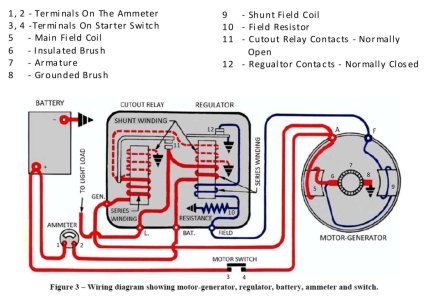
Below is the same wiring diagram as shown above – this time we will study it as the starter generator produces electricity.
1A Delco Remy Two Terminal Motor Generator.jpg
With the Armature (7) now being driven and rotated by the running engine the windings on it are very close and rotating inside the two Field Coils (5) and (6). There will be a little bit of residual magnetism in the pole pieces (pieces of iron) that the wires that make up the two field coils (5) and (9) are wrapped around. As you will note brush (8) is connected to ground as it was when the starter generator was a motor. This bit of residual magnetism will result in a very small amount of electricity being produced inside the windings on the Armature (7). This electricity will result in a slight amount of current being able to flow from the armature to brush (6) and in turn through the Shunt Field Coil (9) since it is connected to ground. The Shunt Field Coil (9) is connected to a ground point from F terminal of the starter generator to the Field terminal of the regulator. Inside the regulator the Field terminal is connected to the regulator contacts (12 which are normally closed completing the circuit to ground. As the current flow in the Shunt Field Coil (9) begins the pole piece will begin to turn into an electromagnet with magnetic properties. Current flow will continue to increase inside the Shunt Field Coil and eventually the starter generator will be capable of producing more current than is required by the Shunt Field Coil (9) and there will be current flow in the winding of the Main Field Coil to the A terminal of the starter generator. This excess current can now flow to the GEN terminal of the regulator which is connected to a winding on the post of the Cutout Relay and the current flow will now increase to the point where the normally open cutout relay contact (11) will close if the speed of the starter generator is increased. The cutout relay post magnetic properties will get strong enough to attract the Cutout arm that the upper part of the contact (11) is mounted on. Once that happens and the cutout relay closes the L terminal and the BAT terminal of the regulator are connected to the A terminal of the starter generator and current can begin to flow to a load such as the lights and also to the battery to begin recharging it to replace the energy that was removed from it during the starting process. It should be noted that the Shunt Field Coil (9) is used to control voltage and current output and the Main Field Coil winding acts more like a heavy gauge wire when the starter generator is used as a generator. As a result the approximately 10 amps of excess current being produced by the starter generator will not make the Main Field Coil pole very magnetic. I will provide pictures later on in the article of the internals of a starter generator to show the difference in the wire thickness that is used.

Now that the starter generator is supplying power to both the battery and any load such as lights the starter generators output needs to be controlled or regulated so that only a certain level of both current and voltage can be produced by the starter generator. This is done by opening and closing the regulator contacts (12) many times a second so that the current flow in the lighter wound field coil (9) can be controlled and temporarily stopped whenever too much current is being supplied or the voltage level at the battery is too high. As current flow or voltage level approaches the designated limits the windings around the regulator post will cause the magnetic pull of the post to increase and eventually attract the arm the lower part of the contacts (12) is mounted on causing the circuit to ground to open. Once the circuit is opened the magnetic properties of the field coil (9) will drop and the starter generator output will drop and the magnetic pull on the arm the lower contact (12) is mounted on will decrease and the contacts will once again close. This cycle of opening and closing the regulator contacts (12) occurs about 200 times per second or more as long as the starter generator is producing power. In normal use this would soon cause the contacts to arc creating pitting very quickly. On the underside of the regulator body is a resistor that is connected from the FIELD terminal of the regulator to ground. This resistor acts as a current absorber so to speak to greatly reduce arcing at the contacts as they open and close since it allows a minimal amount of current to always flow from the field coil winding (9) to ground.

If we examine the heavy windings around the cutout pole and the regulator pole of the regulator you will notice that any current flowing to the battery and the load will control the magnetic strength of both poles – the more current that flows the greater the magnetic pull will be. In the case of the cutout a reduced or reversed current flow will allow the cutout contacts (11) to return to their open state. This is necessary since most starter generators require an engine speed of 1300 rpm or more for the output of the starter generator to be useful to charge the battery and power any load. If the output level is not high enough then current will actually being to flow from the battery to the starter generator. This would discharge the battery if it was allowed to happen for any length of time if the engine was at idle and that would not be good. In the case of the regulator post if current flow to the battery or a load increases to about 10 amps the regulator contacts (12) will open resulting in the output from the starter generator to drop. Similarly if the voltage level at the battery should increase to about 14.4 volts the magnetic pull of the post will increase and the regulator contacts (12) will once again open resulting in the output of the starter generator drop.

This is basically how the starter generator and regulator work together to recharge the battery and power a load such as lights while maintaining the amount of current flowing from the starter generator and the voltage level at the battery to safe levels.
 
For those that missed it earlier a direct current generator does not self limit current output the way an alternator does and as such requires both the amount of current produced and the voltage level of the current produced to be regulated so that both the current and voltage levels remain at safe levels to protect the battery, any loads such as lights and the starter generator!

A few things should now be mentioned that will help you better understand the charging system and how the regulator functions and responds to control the charging system during an engine start up cycle.

A fully charged battery at rest will usually have a voltage level of approximately 12.6 volts. During the starting process a large amount of current (about 125 amps) is drawn out of the battery quickly over a very short period of time (five to ten seconds) by the starter generator. During this process the battery voltage level will drop to as low as 10 volts and now the battery is in a state of discharge and needs to be recharged to replace the energy that was removed. Once the starter generator output reaches a high enough level the cutout contacts will close and the starter generator can begin to replace the energy that was removed from the battery. Since the battery is now in a discharged state it will happily draw as much as 30 or more amps of current to try and replace the energy that was removed. A current draw level of 30 amps would be unacceptable so the voltage regulator must step in and limit the amount of current being produced to an acceptable level of about 10 amps to keep the starter generator from getting too hot. This can be observed if the tractor has an ammeter as shown in the wiring diagram. At this point in time if the voltage level at the battery is measured it will probably be around 12 to 12.5 volts and the regulator is acting in what I will call current limiting mode. As the engine continues running the battery begins to get recharged and after about 3 – 5 minutes the current draw of the battery will drop to about 5 amps and the voltage level at the battery will rise to about 13 to 13.5 volts as the battery gets closer in returning to its fully charged level. At this point in time both the current and voltage levels are acceptable so the regulator is no longer limiting current or voltage very much and is getting close to entering into what I will call voltage limiting mode. After a few more minutes the current level will drop to about 2 - 3 amps to maintain the battery charge level and the voltage level at the battery will be about 14.4 volts as the regulator is now in voltage limiting mode. Most regulators sold for the starter generator systems are still mechanical in nature and may require periodic adjustment. In some service manuals there is information on how to set and adjust the contacts inside the regulator. If you are trying to set the voltage level portion of the regulator it must be done after the battery has had a chance to recharge back up since this will be when the regulator is operating in voltage regulation mode. Do not try and adjust or set the voltage level in the charging system until the engine has been running for at least 15 minutes after starting since until the battery has been recharged and the system is up to operating temperature you will not get a correct setting. This is usually stated in most service manuals but I thought I would mention it since it is important to remember – when the charge rate is high the battery voltage will be low and when the charge rate is low the battery voltage will be high.

If you study the wiring diagram you will see that any current flowing from the starter generator to a load will not pass though the ammeter portion of the circuit since the L terminal and BAT terminal are connected internally inside the regulator. The ammeter will only show current that is flowing to or from the BAT terminal of the regulator to the positive terminal of the battery. This is why if the battery is discharged and the lights are turned on the ammeter will show a discharge with the engine not running. If the engine is running and the lights are turned on and the battery is discharged the charging rate shown on the ammeter will drop and now only show the amount of current that is now flowing to the battery. For example say the battery was discharged and the ammeter showed 10 amps with the lights off. Let us say the lights draw 5 amps of current to illuminate them and the ammeter is displaying a charge rate of 10 amps with the lights off as mentioned above. If the lights are turned on the ammeter reading will now drop to about 5 amps since the generator is still producing 10 amps but only 5 amps is passing though the ammeter circuit to recharge the battery. Most starter generator systems are wired similarly to this but a wiring diagram should be obtained for the particular tractor you are working on to verify the wiring connections.
 
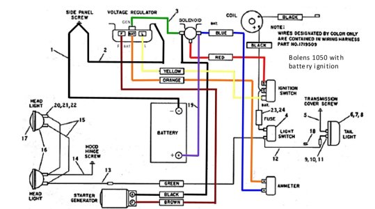
For comparison here is a wiring diagram for a Bolens 1050 garden tractor using a starter generator. As you can see there are a few differences which we will now discuss.
2A Bolens 1050 Wiring Diagram.jpg
You can see that the normally open push button starter switch has been replaced with a starter solenoid that is controlled by the ignition switch. Power for the ignition switch is provided by the regulator through the L (Load) terminal on the regulator. Since the ignition switch provides power for the lights and also for the battery ignition circuit I have referred to the L terminal as a Load rather than lights. Any current that flows from the starter generator to the ignition switch (Load) when the cutout relay is closed will not pass through the ammeter in this system either. If however current flows from the battery to the lights or ignition a discharge reading will show on the ammeter. Instead of running a separate wire from the GEN terminal of the regulator all the way to the A terminal of the starter generator a wire is connected from the GEN terminal of the regulator to the starter side terminal of the solenoid and the starter cable connects from that point to the A terminal of the starter generator. In summary this is very similar to the first wiring diagram we saw – your tractor will probably be similar but not exactly the same as either of these diagrams.

Before we move on to testing a starter generator I think it is a good idea that the reader see an actual regulator and starter generator and some of the components inside to get a better understanding of these components.
 
A Peak inside a Mechanical Regulator

Commonly referred to as a voltage regulator it should be remembered that the regulator serves three important functions. First it only allows current to flow between the GEN terminal on the regulator and the starter generator when the starter generator is being used as a generator and only when it is capable of providing useful current. If the generator is not capable of supplying a level of current high enough to be useful the regulator must prevent any current flow from the battery to the starter generator – other wise the starter generator will act like a motor and drain the battery. This function is the job of the cutout relay with a set of normally open contacts. Second the regulator must keep the current level coming from the starter generator to an acceptable level so that it does not overheat. Third the regulator must keep the voltage level at the battery and charging system at an acceptable level. If the voltage level is allowed to get too high then the electrolyte inside the battery may begin to boil and light bulbs could burn out. The regulator section with a set of normally closed contacts is used to accomplish both current and voltage regulation.
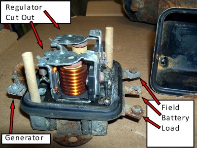
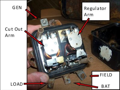
Here are a few pictures of what is usually hidden underneath the cover and the bottom of the regulator.
1 Regulator With Cover Removed.jpg2 Regulator With Cover Removed.jpg
Here you can see the four terminals and the cutout and regulator sections. The terminals are usually labelled GEN (for the wire from the generator Armature terminal), F or FIELD (for the F terminal on the generator, BAT (for the wire that connects to the positive battery terminal) and L (for a connection to any accessories that will act as a load). It should be noted that sometimes the GEN terminal is located on the bottom of the regulator body and not easily seen. The cutout relay has a set of normally open contacts that close when the generator reaches a current output level where it is capable of supplying useful current level to the battery and any accessories. The regulator relay has a set of normally closed contacts that open when current output or voltage reaches a level that is too high for the components in the charging system to operate safely.
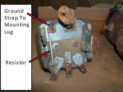
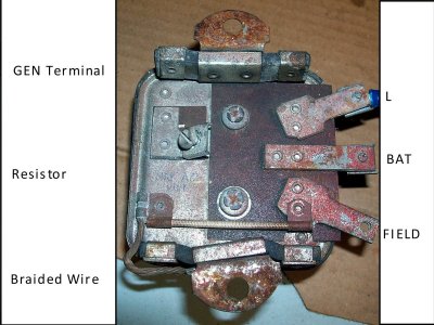
3 Bottom Of Regulator.jpg4 Bottom Of Regulator.jpg
In the third and fourth picture you can see the resistor that is between the FIELD terminal of the regulator and the regulator body and the braided wire that connects the rubber mounted regulator body to the mounting lug where it completes the ground circuit. In the third picture the rubber mounting strap is rotten and the mounting lug is just hanging from the braided wire. In the fourth picture you can see that the GEN terminal is located underneath the regulator body. If the resistor is isolated and measured with an ohm meter it should show a resistance value of approximately 60 – 75 ohms. To isolate the resistor a piece of paper or cardboard can be placed in the regulator contacts and any wiring disconnected from the Field terminal on the regulator. Then an ohmmeter can be used to measure the resistance between the Field terminal and the body of the regulator.
 
A Peak inside a Mechanical Regulator

Commonly referred to as a voltage regulator it should be remembered that the regulator serves three important functions. First it only allows current to flow between the GEN terminal on the regulator and the starter generator when the starter generator is being used as a generator and only when it is capable of providing useful current. If the generator is not capable of supplying a level of current high enough to be useful the regulator must prevent any current flow from the battery to the starter generator – other wise the starter generator will act like a motor and drain the battery. This function is the job of the cutout relay with a set of normally open contacts. Second the regulator must keep the current level coming from the starter generator to an acceptable level so that it does not overheat. Third the regulator must keep the voltage level at the battery and charging system at an acceptable level. If the voltage level is allowed to get too high then the electrolyte inside the battery may begin to boil and light bulbs could burn out. The regulator section with a set of normally closed contacts is used to accomplish both current and voltage regulation.
Here are a few pictures of what is usually hidden underneath the cover and the bottom of the regulator.
View attachment 77578View attachment 77579
Here you can see the four terminals and the cutout and regulator sections. The terminals are usually labelled GEN (for the wire from the generator Armature terminal), F or FIELD (for the F terminal on the generator, BAT (for the wire that connects to the positive battery terminal) and L (for a connection to any accessories that will act as a load). It should be noted that sometimes the GEN terminal is located on the bottom of the regulator body and not easily seen. The cutout relay has a set of normally open contacts that close when the generator reaches a current output level where it is capable of supplying useful current level to the battery and any accessories. The regulator relay has a set of normally closed contacts that open when current output or voltage reaches a level that is too high for the components in the charging system to operate safely.
View attachment 77580View attachment 77581
In the third and fourth picture you can see the resistor that is between the FIELD terminal of the regulator and the regulator body and the braided wire that connects the rubber mounted regulator body to the mounting lug where it completes the ground circuit. In the third picture the rubber mounting strap is rotten and the mounting lug is just hanging from the braided wire. In the fourth picture you can see that the GEN terminal is located underneath the regulator body. If the resistor is isolated and measured with an ohm meter it should show a resistance value of approximately 60 – 75 ohms. To isolate the resistor a piece of paper or cardboard can be placed in the regulator contacts and any wiring disconnected from the Field terminal on the regulator. Then an ohmmeter can be used to measure the resistance between the Field terminal and the body of the regulator.
Much of what is shown here easily relates to Japan vintage tractor electrical systems as well. Bolens even has re-badged Iseki/Mitsubishi tractors from Japan as well.

The VR looks very much the same. Today there are solidstate versions. Will you demonstrate the modern VR in this series too for this reported documentation. The VR you had shown is a 4-terminal type typical of The Ford/Shibarura, Yanmar/Deere, Iseki/Mitsubishi, and othersof the 70s, 80s and some 90s machines. There are also 6-terminal types like the VR-550.
I am trying to keep the information I am presenting limited as to what a person might encounter on a North American garden tractor using a Delco Remy starter generator with an original style mechanical regulator. I believe that member MNGB has done a few threads where he used an aftermarket solid state regulator on a starter generator - I believe they were made to work with older Harley Davidson motorcycle Delco Remy generators if I remember correctly. I am not familiar with Japan vintage tractor electrical systems that used the 4 and 6 terminal regulators for direct current generators but feel free to add information about them in this thread since that is how we all learn. Did the rebadged Iseki/Mitsubishi tractors use starter generators or were they the newer PM alternator style charging systems with separate starter motors?

I did take an old mechanical regulator body for a starter generator and removed the inner components and converted it to an electronic version using a circuit that a gentleman in Chile had posted on his web site - the circuit he designed was originally used with a 20 amp starter generator (Dynastarter) in a marine application. I modified the circuit he designed so it would regulate the current level at a lower level of about 10 amps and mounted most of the components on a piece of perf board and then mounted the perf board and a few other components (sense resistor, diode, switching Mosfet transistor, etc.) inside the regulator. With the cover installed the unit looks original on my Bolens 1053 but with the cover removed you can see the electronic circuitry. I had originally tried using a GM 2 wire alternator regulator but it would not limit the current output and only controlled the voltage level. If you are interested you can view a detailed thread I did on the regulator construction I did for a starter generator on another site - here is a link to it -
Electronic Voltage Regulator For Bolens 1053 Project
 
A Peak Inside A Starter Generator

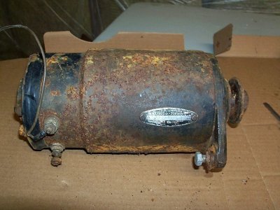
The following pictures were obtained while I repaired a Delco Remy starter generator tag number 1101970 – other starter generators may vary. Some of the early starter generators used a bronze bushing rather than a bearing to support the brush end of the Armature shaft. On these units there is usually an oil hole that can be used periodically to lubricate the bushing and shaft area. If your unit has a bushing follow the owner’s manual for your garden tractor to determine how often this area needs lubrication as applying too much oil may contaminate the brushes and commutator area resulting in poor operating performance.

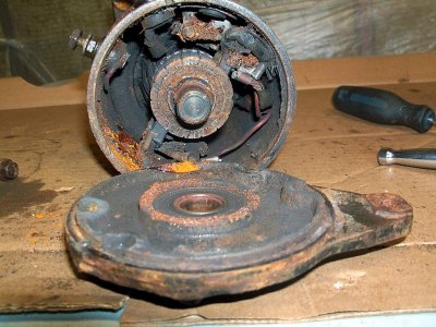
I will show a brief summary of how the unit comes apart and then detailed pictures and information of how the unit was put back together. Here is the starter generator unit when I started – the Armature was rusted to the pole pieces inside and would not turn. I removed the two long bolts that hold the end plates together at each end of the main housing body and then removed the rear plate.
1 1101970 Starter Generator.jpg2 Rear Plate Removed.jpg
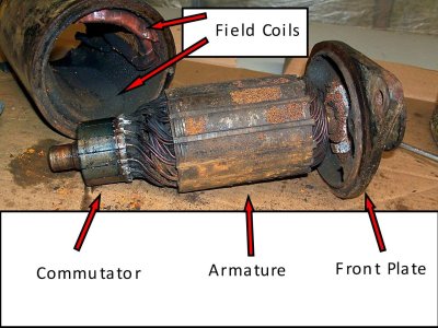
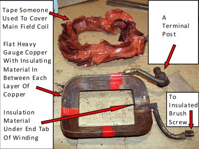
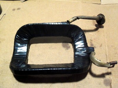
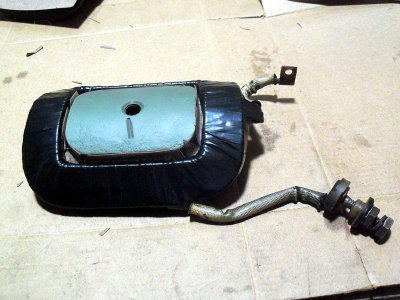
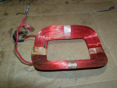
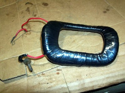
I removed the two brushes, the brush arms and springs and eventually I was able to gently tap the armature out the front of the housing using a wooden hammer - you can see the rust that had formed on the armature. Due to the rust that had formed inside the housing I removed the Field Coils so I could use a wire brush to remove all the rust and clean everything up. As you can see someone had applied some sort of tape to insulate the Main Field Coil.

3 Armature Removed.jpg4 Main Field Coil.jpg

Be gentle while removing the nuts and insulator pieces that hold the A and F terminal post in the housing as the posts are soldered to the field coils.

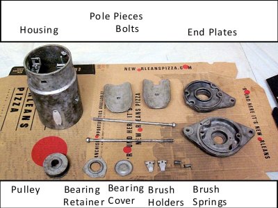
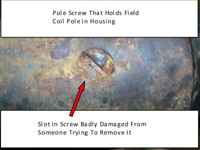
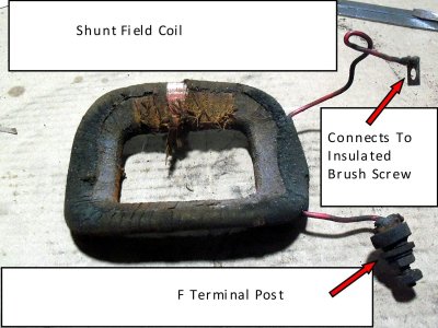
Here you can see the Shunt Field Coil that I removed and also the main components that make up the starter generator after I got them cleaned up. Each pole piece is held inside the main housing using a tapered head slotted screw and the two screws on this unit had been severely damaged by someone using too small of a flat screwdriver to try and remove the screws.

5 Shunt Field Coil.jpg6 Components Of Starter Generator.jpg

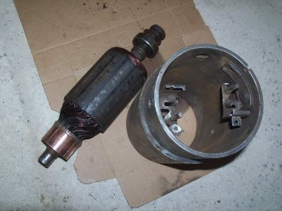
Here is the Armature and a look inside the housing after I got them cleaned up – I did not want to get too aggressive with the Armature and risk damaging the insulation on the wire windings. You can also see the head of one of the damaged screws where someone has slipped in the flat slot. If you try to remove these screws and do not have a large flat screwdriver I would suggest getting a piece of 1/8” or 3/16” thick x 3/4” wide flat steel about 2” long and then using a file to shape the end so it is a good fit inside the screw slot. Then clamp at pair of vise grips at 90° to the flat steel very close to the shaped end and place the flat steel piece into the slot. Then gently tap on the top end of the flat steel with a hammer and try rotating the flat steel counter clockwise (the screws are right hand thread) while continually tapping on the end and see if the screw moves. If it does not then you could try hitting the head of the screw directly on the end with a large punch and hammer a few times to disturb any rust that might be holding the screw. Then use a hammer and a 1/4” diameter flat punch located at the very end of the slot and held at about a 90° angle to catch the slot and try driving the screw counterclockwise to start it to rotate. Once it moves it should thread out of the hole easily.

7 Armature And Housing With Field Coils Removed.jpg8 Pole Screw Slot Damaged.jpg
 
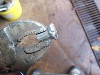
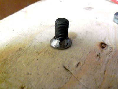
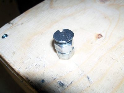
Due to the condition of the screws I had to use the punch method and I ended up welding them on the ends to build the metal back up, file the weld back down and then used a hacksaw blade to reform the slot.
9 Screw Head Welded.jpg10 Weld Levelled With A File.jpg
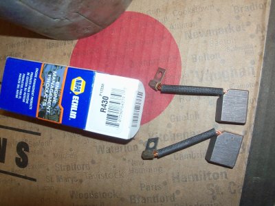
This shows one of the screws after I was finished – depending on your welding skills you may be able to do something similar if necessary or simply purchase new screws. This is the part number of the new brushes I ordered from my local Napa store – as of 2023 they still show as being available. If your unit is a different number than 1101970 they may or may not fit your application and there are other sources for parts for these units.
11 Slot Reformed.jpg12 New Brush Set.jpg
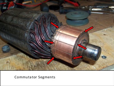
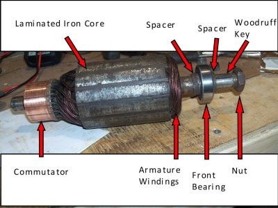
Here you can see the different components that make up the Armature – the commutator segments must be smooth for the brushes to make good contact with them. The nut at the front of the shaft is a special thread so be careful when removing it so that you do not damage the threads on it or the armature. It is usually not necessary to remove the nut unless you are replacing the front plate, the front bearing, the armature, the pulley or want to clean up the spacers. In my case the woodruff key slot was badly damaged and the bearing was not the best so the nut got removed and everything cleaned up.
13 Commutator Segments On Armature.jpg14 Armature.jpg
 
Attached is a picture of a tool made specifically to remove the screws that hold in field coils. Probably pricey and perhaps hard to find in todays world but something homemade could probably be figured out with a bit of thought.
 

Attachments

  • Disassembly Instructions.jpg
    Disassembly Instructions.jpg
    243.2 KB · Views: 3
  • Pole Shoe Spreader And Screwdriver Tools.jpg
    Pole Shoe Spreader And Screwdriver Tools.jpg
    184 KB · Views: 3
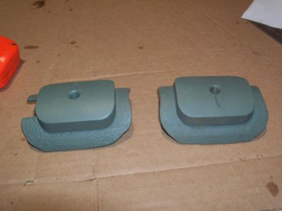
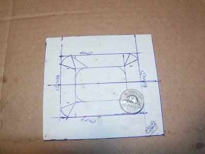
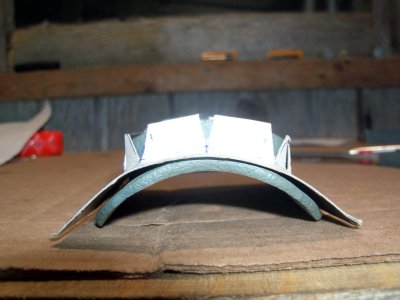
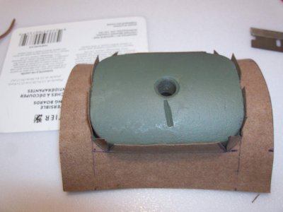
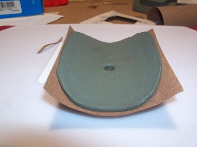
Here you can see the two pole pieces and a cardboard template I made so I could create new insulation pieces out of 1/64” thick gasket paper to protect the field coil insulation from damage where it pressed against the pole piece metal. As you can see one of the pole pieces has a notch cut in it so make sure if you remove the field coil poles that you install them back in the correct location. Take lots of pictures if you are taking the starter generator apart makes it easy to reference how things were when it comes time to put things back together.
15 Pole Pieces With Coat Of Primer.jpg16 Cardboard Pattern To Make Insulator For Pole Pieces.jpg
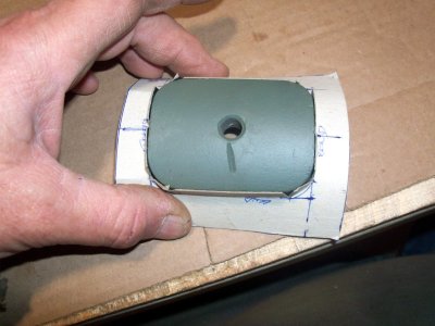
Here the cardboard template is test fitted to make sure it fits the pole pieces.
17 Test Fit Of Cardboard Pattern On Pole.jpg18 Test Fit Of Cardboard Pattern On Pole.jpg
Once you are happy with the template fit new insulators can be cut from a piece of 1/64” gasket paper to form new insulator pieces.
19 Insulator Made Out Of One Sixty Fourth Gasket Paper.jpg20 Insulator Made Out Of One Sixteenth Gasket Paper.jpg
 
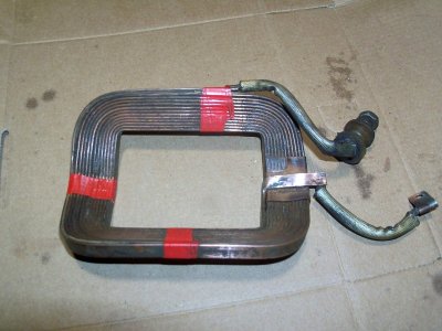
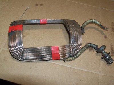
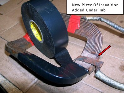
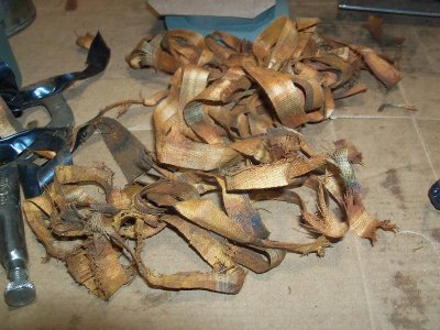
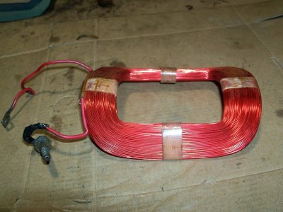
Here are pictures of the Main Field Coil with the insulation removed. I believe that originally the insulating tape would have been similar to what the Shunt Field Coil was wrapped in but someone had used a plastic form of tape to wrap the Main Field Coil windings with. I removed it to inspect and clean up the heavy flat copper winding that make up the Main Field Coil. The winding can best be described as a flat strip of copper approximately 1/16” thick X 1/4” wide formed into the shape of the field coil winding. The thickness of the copper and the way it is connected in the circuit differentiates the Delco Remy starter generator from a conventional Delco Remy generator in my opinion. There is an insulation paper that is in between each winding layer and after using a Scotchbrite pad the insulation and the winding looked good – I did add a new thin piece of gasket paper where the inner winding tab comes across the windings. Since the heavy copper strip is not insulated like the thinner magnet wire of the shunt field coil any rust or metal could partially short the windings so if you remove the insulation make sure you remove any debris before rewrapping it with new insulating tape.
21 Main Field Coil With Insulating Tape Removed.jpg22 Main Coil Cleaned Up Lightly With Scotchbrite.jpg23 Main Coil Cleaned Up Lightly With Scotchbrite.jpg
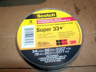
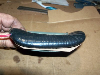
I used 3M Super 33 tape which worked well for me but there are probably other products that would work as well or better. I did two layers as any more and the tape may make the field coil to fit back in between the pole and the housing properly. Keep the overlap uniform to get a nice smooth layer but do not pull too hard trying to stretch the tape as that may distort the field coils shape.
24 Tape.jpg25 Starting To Cover Coil With New Tape.jpg
Main Field Coil taped and test fit on pole piece.
26 Coil Taped.jpg27 Main Coil Ready To Reinstall.jpg
 
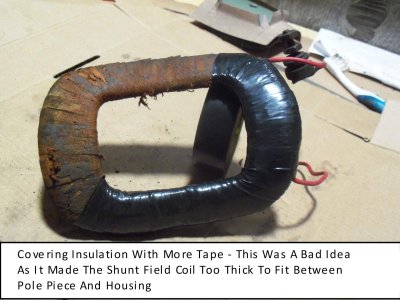
Here are pictures of the Shunt Field Coil – the insulation on this coil looked to just have one spot where the insulation was damaged so I thought I could just add a layer of tape overtop.
28 Shunt Field Coil.jpg29 Covering With More Tape - Bad Idea.jpg
This was a bad idea as the field coil was now too thick to fit properly so I ended up removing the new tape and the original insulating tape.
30 Result With Tape Over Existing Insulation.jpg31 Tape Removed From Shunt Field Coil.jpg
As you can see the Shunt Field Coil windings are much thinner than the Main Field Coil using conventional magnet wire.
32 Shunt Field Coil Windings.jpg33 Shunt Field Coil Windings.jpg
 
Last edited:
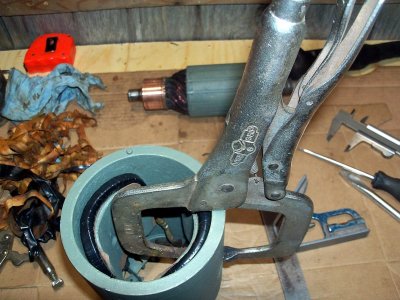
The Shunt Field Coil got taped with new tape and test fitted on the pole piece – this time things looked good other than the tape resulted in the coil shape deforming slightly. As a result a pair of C Clamp vise grips was used to draw the pole piece flat against the inside of the housing so the screw could be started easily.
34 Shunt Field Coil Retaped.jpg35 Using C Clamp Vise Grips So I Can Start Screw.jpg
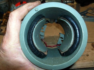
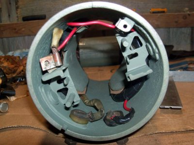
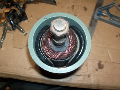
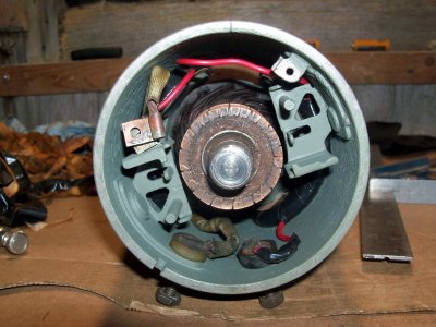
Here is how the pole pieces and field coils looked as viewed from each end of the housing.
36 Field Coils Ready For Last Tighten Of Screws.jpg37 Field Coils Ready For Last Tighten Of Screws.jpg
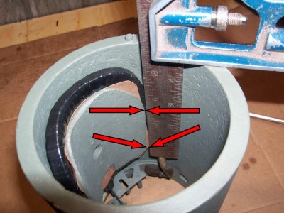
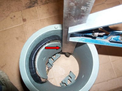
It is very important the pole pieces are square with the Armature as being off slightly can result in the pole piece rubbing on the Armature after the unit warms up and things expand. A small square can be used to check how the edge of the pole piece looks in relation to the end of the housing. In the picture with four arrows the edge is off so the pole piece got rotated slightly before final tightening of the pole piece screw.
38 Pole Piece Needs To Be Rotated Slightly.jpg39 After Rotation.jpg
 
A test fit was then done by inserting the Armature inside the housing to make sure there was a little bit of wiggle room between the pole pieces and the Armature.
40 Test Fit Of Armature Inside Pole Pieces.jpg41 Test Fit Of Armature Inside Pole Pieces.jpg
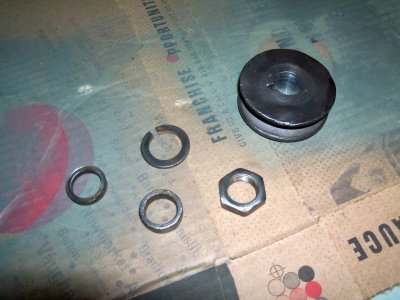
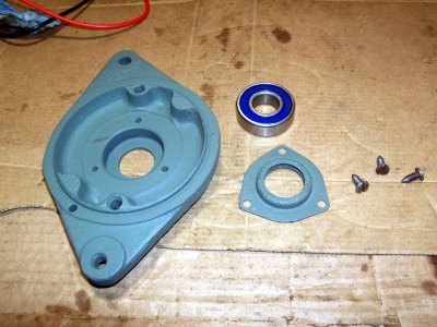
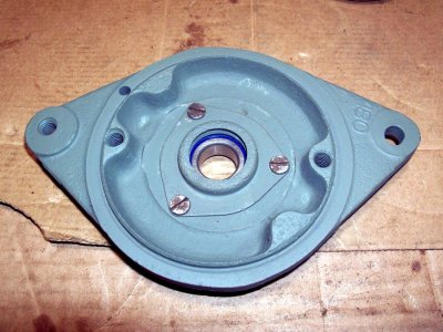
Here the pulley, spacers, lock washer and nut have been cleaned up as well as the front plate and retainer. A new bearing was installed in the plate and then the retainer was installed using the three small screws.
42 Pulley Bushings Lock Washer And Nut.jpg43 Front Plate Bearing And Bearing Retainer.jpg
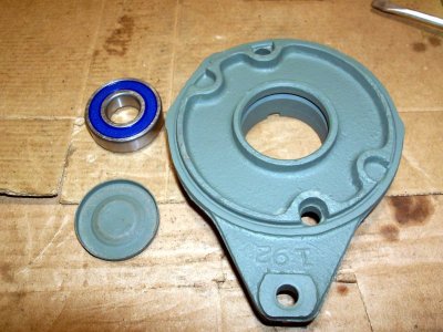
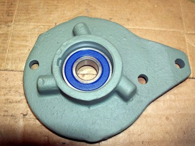
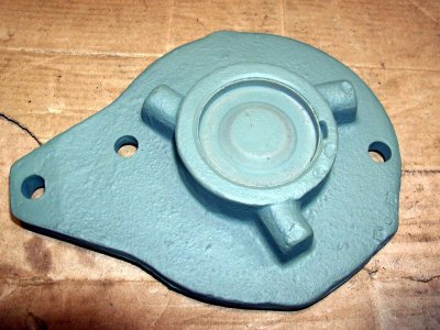
Then the rear plate, bearing and cap were next to be assembled.
44 Bearing And Retainer Installed.jpg45 Rear Plate Bearing And Cap.jpg
 
The new bearing was set in place and the end cap piece installed.
46 Bearing Installed.jpg47 Cap Installed.jpg
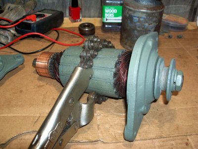
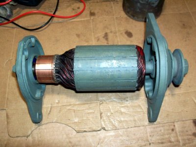
A chain vise grip was used to hold the Armature while the front plate, spacers, woodruff key, pulley, lock washer and nut were installed and the nut tightened. A nylon strap wrench might be a better choice to hold the armature from turning but the chain vise grip worked for me. Then the rear plate bearing was slid onto the rear shaft to see that the armature rotated true and without any noise.
48 Using Chain Vise Grips To Hold Armature.jpg49 Checking For Any Noise Or Bend.jpg
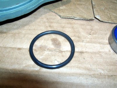
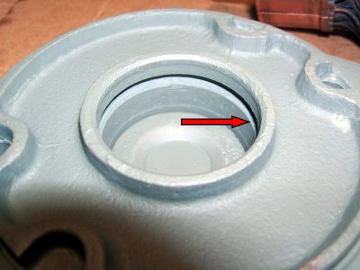
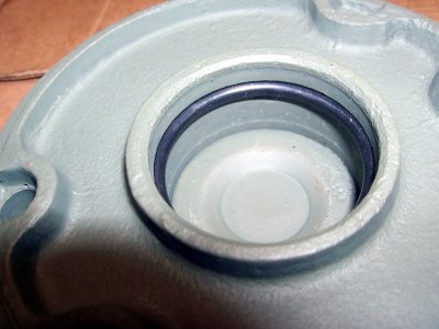
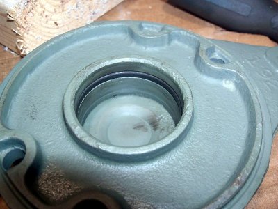
There is a groove in the rear plate where the bearing sits that had an O ring in it on my unit. I am not sure the O ring was original as I have not seen one in any of the parts lists I have found. I sourced a new O ring that looked like it would do the job but when I tried to install the bearing I found it was too tight.
50 O Ring For Rear Plate Groove.jpg51 Groove In Plate.jpg
 
I cleaned up the original O ring and it appeared to be more of a square cut design so I ended up using it.
52 Checking Fit In Groove.jpg53 Old O Ring Cleaned Up And Installed.jpg
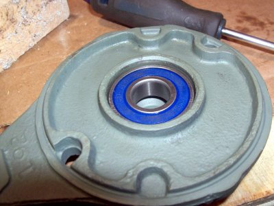
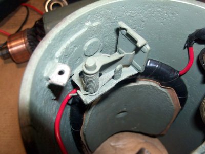
With the old O ring in place the bearing slid in fine. The brush arms and springs were installed.
54 Bearing Installed With Oring In Place.jpg55 Grounded Brush Arm And Spring Installed.jpg
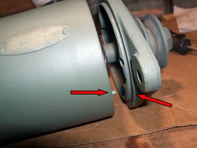
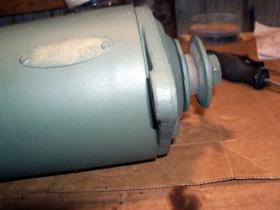
There is an alignment pin on the front of the housing that aligns with a hole in the front plate. Once these are aligned the front plate will fit flat against the housing.
56 Pin In Housing Must Align With Hole In Front Plate.jpg57 Plate Fits Flat On Housing.jpg
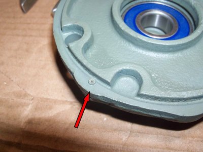
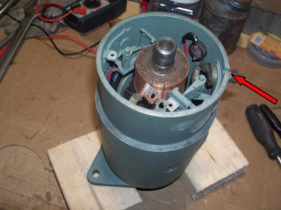
There is also a similar alignment pin on the rear plate and a notch in the housing that it must fit into so the rear plate will fit flat against the housing and be correctly oriented.
58 Alignment Nipple On Rear Plate.jpg59 Alignment Notch In Housing.jpg
 
Back
Top